Because analog I/O has data than can just fit in a single 16-bit word, you need to have a special instruction to get the data into/out of the modules, instead of just being able to look at the data table (You probably knew that, but I'm writing for lurkers too - forgive me if I get too simplistic).Those instructions are the Block Transfer Write (BTW) and Block Transfer Read (BTR). These instruction transfer a block of data (up to 64 words) from the PLC to a module (BTW) or from the module to the PLC (BTR).
In general, each (analog) I/O module needs a BTW/BTR pair, one for configuration, the other for data. If, for example, you have an analog input module, you would execute a BTW instruction on the powerup scan (or if data from the BTR indicated that the module had somehow lost it's configuration) to give it all the parameters that it needs to return data correctly (number of channels, format of data (2's complement, BCD), range for each channel (typically 0-4095, but some folks like to bring in the Input in engineering units))
Then, on all other scans, the BTR instruction will be executed to read all the channel data.
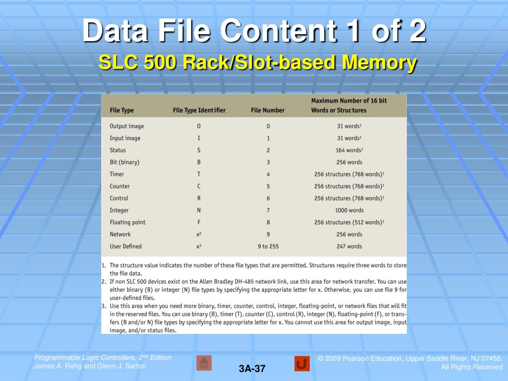
The BTR and BTW instruction need two blocks of register addresses in order to work: a control register, and a data register. The control register can be either a BT type (preferred), or an integer type (if you're dealing with older PLCs, or SLCs). The data register must be an integer type (although as I look at the Help file, I see an Input type shown in the example - I have no idea why they would do that!).
The control registers contains all the housekeeping info for making the instruction work - the status bits, the Rack/Slot/Group address (shown on the instruction), and other stuff that is frankly unimportant.
The data registers contain the data that is to be transferred in one block. If it's the BTW to that Analog input, it would contain the number of channels, format of data, etc. If its the BTR from the AI, it would contain some header info (typically about 5 words), followed by the current readings (scaled in the manner that you configured the module with the BTW).
Now for the easy part. In the bad old days, we had to set up the configuration by hand, making sure that all 22 words of data sent to configure an analog input were just right. RSLogix has made it easy with the IO CONFIGURATION, near the top of the project window on the left.
Double Click on IO CONFIGURATION. Double click on the Chassis Type (or right click and Add a Chassis). Configure your rack to the correct size. Point to the slot on the chassis where you will have a module, right click and select Add Module. Pick the part number. Once the part number is in the correct spot, right click and select Display Module (or just double click), and you will be presented with a dialog box for entering the Config and Data registers for both the BTW and BTRs. Enter them if you've already decided what they should be, or just pick Auto-pick (I've never been happy with the addresses they auto-assign, but that could just be me), and it will bring up a helpful window. This window allows you to just pick the setting that you want, and shows where the data will be located for programming. (If you were live with the PLC, it would show that actual raw data).
You can use the Insert Ladder Rungs button to have RSLogix make the proper ladder code for the BTW and BTR rungs. Play around with this screen and the settings and you'll get a good feel for what's going on in the BTR/BTW.
You can access this screen quickly by clicking on 'Setup Screen' on the BTR or BTW instruction.
Good luck, if you have any more specific questions, just ask,
Allen
©¿©¬


